K’NEX gears can transfer turning motion, change its direction, increase or reduce speed, and change the available turning force. By combining different gears, rods and chains, you can build anything from a simple hand-driven fan to a clock, mixer, vehicle or lifting mechanism.
How to Use This Page
The first part of this page explains in simple steps how gears transfer motion and change direction, speed and turning force. It is suitable for students, beginning builders and anyone discovering K’NEX gears for the first time.
After Want to explore further?, the page continues with more detailed information for experienced builders, teachers and collectors. This section explains gear ratios, compound gear trains, attachment methods, part numbers and special gear types.
You can read the page from beginning to end or go directly to the section that matches what you want to learn, build or identify.
How Gears Work
A gear is a wheel with teeth around its edge. When the teeth of two gears mesh, turning one gear makes the other gear turn.
Gears are often hidden inside everyday objects. They can be found in clocks, hand mixers, wind-up toys, drills and many other machines. Bicycles use toothed wheels and a chain to transfer motion from the pedals to the rear wheel.
Driver and Driven Gears
The gear you turn first is called the driver gear. It transfers motion to the next gear, called the driven gear.
When two gears mesh directly, they turn in opposite directions. If the driver turns clockwise, the driven gear turns counterclockwise.
Try this with two K’NEX gears:
- Turn one gear slowly.
- Watch the direction of the second gear.
- Reverse the direction of the driver.
- Make the second gear the driver and observe what changes.
Adding an Idler Gear
Two or more meshing gears form a gear train. A gear placed between a driver and a driven gear is often called an idler gear.
With three gears in a row:
- the first and second gears turn in opposite directions;
- the second and third gears also turn in opposite directions;
- the first and third gears therefore turn in the same direction.
An idler changes the direction of rotation, but in a simple gear train it does not change the final theoretical speed ratio. Its size may help the gears fit into the available space, but the ratio between the first and last gears remains determined by those two gears.
Faster or More Powerful?
The relative sizes of the driver and driven gears determine their speeds.
When a large driver gear turns a smaller driven gear, the smaller gear rotates faster. This is called gearing up.
When a small driver gear turns a larger driven gear, the larger gear rotates more slowly but can provide more turning force. This is called gearing down.
A gear system cannot increase both speed and turning force at the same time:
- increasing speed reduces the available turning force;
- increasing turning force reduces speed.
In real models, some energy is also lost through friction, movement between parts and gears that do not mesh perfectly.
Think of a Bicycle
A bicycle transfers motion using sprockets and a chain. When you turn the pedals, the front sprocket pulls the chain. The chain then turns the sprocket connected to the rear wheel.
Unlike two gears that mesh directly, sprockets connected by an uncrossed chain rotate in the same direction. A chain can also transfer motion between axles that are some distance apart.
Different bicycle gears help the rider choose between speed and turning force:
- a higher gear can make the bicycle travel farther for each turn of the pedals, but requires more force;
- a lower gear makes the bicycle travel less far for each turn, but makes it easier to start or climb a hill.
K’NEX chains are assembled from separate links. Every link must face in the same direction so that the chain can move smoothly.
Turning a Corner
Most ordinary gears mesh while their rods remain parallel. Sometimes motion must be transferred between axles that point in different directions.
A hand mixer or hand-operated drill is a familiar example. You turn a handle around one axle, while another part of the machine rotates around an axle at a right angle to it.
A K’NEX crown gear has raised, sideways-facing teeth. These allow it to mesh with another gear at an angle of 90 degrees. This changes the direction of the axle as well as the direction of the motion.
From Rotation to Straight-Line Movement
A mechanism can also convert rotation into another type of movement.
A turning handle might:
- move a window up or down;
- move a part backward and forward;
- turn the hands of a clock at different speeds;
- move the legs or wings of a wind-up toy;
- operate the beaters of a mixer.
Gears therefore do more than make other wheels rotate. They form part of mechanisms that control how an entire model moves.
Build, Predict and Test
Build two parallel rods with a K’NEX gear on each rod. Before turning them, predict:
- Which direction will the second gear turn?
- Will it turn faster, slower or at the same speed?
- What changes when you swap the driver and driven gears?
- What happens when you add an idler gear?
- Can you arrange two gears so that their rods are at right angles?
- Can you transfer motion over a distance using a chain?
Test each prediction and record what you observe. A useful engineering journal can include a drawing of the model, arrows showing movement, your prediction, your observations and your conclusion.
Keep fingers, hair and loose clothing away from motorized gears and other moving parts.
Want to explore further? Continue below to compare K’NEX gear types, calculate speed relationships and identify gears by their shape, size, number of teeth and part number.
Understanding K’NEX Gear Ratios
The number of teeth determines how far one gear turns another.
A standard small K’NEX gear has 14 teeth. The familiar medium gear has 34 teeth.
When a 34-tooth driver turns a 14-tooth driven gear:
34 ÷ 14 = approximately 2.43
The small driven gear therefore makes approximately 2.43 revolutions for every complete revolution of the medium driver gear.
When their roles are reversed:
14 ÷ 34 = approximately 0.41
The medium driven gear then makes approximately 0.41 of a revolution for every complete revolution of the small driver gear.
Because the notation of a “gear ratio” can vary, it is clearest to identify the driver and driven gears and state how many turns the output makes for each turn of the input.
Speed and Turning Force
A large gear driving a small gear increases output speed but reduces available output torque.
A small gear driving a large gear decreases output speed but increases available output torque.
Torque is the technical term for the turning effect of a force. On a simple introductory page, it can also be described as turning force.
The theoretical torque relationship is the inverse of the speed relationship. Actual results differ because real K’NEX models have friction, slight flexibility and movement between their components.
Compound Gear Trains
A simple row of gears does not automatically produce an increasingly large speed change. In a simple gear train, intermediate idler gears mainly transfer motion and determine the final direction.
A larger overall change can be created with a compound gear train. In this arrangement, two gears are fixed to the same axle. They rotate together, and one of them drives the next stage.
The ratios of the individual stages are multiplied. This allows builders to create much larger speed reductions or increases than one pair of gears could provide.
Compound gear trains are useful in clocks, lifting mechanisms and models that require either very slow movement or very high speed.
Types of Classic K’NEX Gear
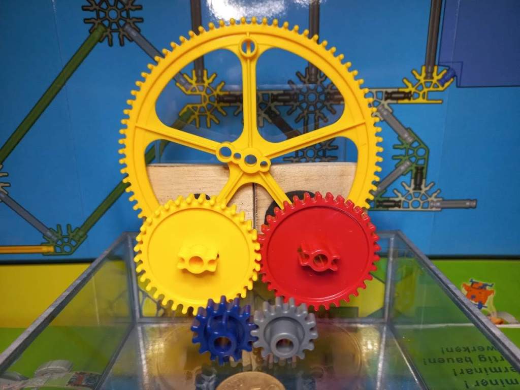
K’NEX produced several gears with different sizes, tooth arrangements and methods of attachment. Parts that look similar may behave differently on a rod.
Standard Small Gear
The standard small gear is approximately 1 in. (25 mm) in diameter and has 14 teeth.
Known part numbers include:
91313– gold;91317– mid blue;99117– blue or dark blue;91317D– dark blue.
The center hole fits over a Classic K’NEX rod. Grooves around the center allow the gear to be locked to the rod with a tan interlocking clip. When locked, the gear and rod rotate together.
Colors and part numbers may vary between production periods and sets.
Push-On Gear
The gray push-on gear 90988 is also approximately 1 in. (25 mm) in diameter and has 14 teeth.
It can be pushed directly onto a Classic K’NEX rod and grips the rod without requiring a separate interlocking clip. It is useful when a compact attachment is needed.
The push-on gear should not be confused with the snap-on gear. Although they are similar in size, they attach and function differently.
Snap-On Gear
The snap-on gear fits onto the end of a Classic K’NEX rod instead of sliding along its full length.
Known part numbers include:
91324– light gray or black;99119– black.
It is approximately 1 in. (25 mm) in diameter and has 14 teeth.
The snap-on gear can rotate freely on the end of the rod. This makes it especially useful as an idler gear or in a gear train where several gears must rotate independently on their supporting rods.
Medium Gear
The red medium gear 90985 is approximately 2.2 in. (55 mm) in diameter and has 34 teeth.
It is a standard spur gear: its teeth point outward around the edge and mesh with another gear operating in the same plane. It can be secured to a rod with an interlocking clip.
The 34-tooth medium gear and 14-tooth small gear form one of the most useful K’NEX gear combinations.
Medium Crown Gear
The medium crown gear is approximately 2.2 in. (55 mm) in diameter and has 34 teeth.
Known part numbers include:
90993– yellow;91993– gray or silver.
Its raised crown teeth allow it to transfer motion between rods placed at right angles. Depending on the arrangement, it can also be used in a gear system with parallel rods.
Partial Crown Gear
The partial crown gear 91700 is a less common medium-sized gear, usually found in orange.
Its outer teeth combine a regular and raised crown-like profile. It is therefore commonly described as a partial crown gear or half-crown gear.
It has a central hole for a Classic K’NEX rod and grooves for an interlocking clip. Its unusual tooth profile makes it useful for special mechanisms and visually distinguishes it from both the ordinary medium gear and the full medium crown gear.
The precise tooth count should be confirmed from a verified physical example before being stated as definitive.
Large Crown Gear
The large crown gear is approximately 5.1 in. (130 mm) in diameter. Most reliably documented examples have 82 teeth.
Known versions include:
90997– black, with a centered rod hole;90998– yellow, with a centered rod hole;91998– yellow, with a centered rod hole and an additional offset hole near the rim.
Black versions with an additional offset hole have also been observed, but their official part number has not yet been confirmed.
The extra hole near the rim can be used as an eccentric connection point. As the gear rotates, a rod attached at this point travels in a circle. A linkage can convert this movement into a rocking, pumping or backward-and-forward motion.
With an 82-tooth large gear driving a 14-tooth small gear:
82 ÷ 14 = approximately 5.86
The small gear therefore rotates approximately 5.86 times for every revolution of the large driver gear.
Large Gears with 82 or 84 Teeth
Most reliably documented black and yellow large crown gears have 82 teeth. An 84-tooth large gear is used in K’NEX educational explanations, and physical 84-tooth examples have been reported.
However, no reliable source has yet connected an 84-tooth black or yellow crown gear to a confirmed part number, set or production period.
The two tooth counts should therefore not be treated as interchangeable:
- 82 teeth is the usual documented count for the large black and yellow crown gears;
- 84 teeth is confirmed for the outer ring of the green multi-track gear;
- 84-tooth black or yellow crown gears are reported, but their exact identification remains uncertain.
A physical gear can be checked by counting the teeth. Some examples may also have a molded tooth-count marking.
Multi-Track Gear
The green multi-track gear 90996 is approximately 5.1 in. (130 mm) in diameter.
It provides more than one gear track:
- 84 teeth on the outer ring;
- 64 teeth on the inner ring.
The outer ring forms an exact 6:1 relationship with a 14-tooth small gear:
84 ÷ 14 = 6
The different tracks give advanced builders more options for positioning gears and constructing compound mechanisms. The multi-track gear is uncommon and should not be confused with the more familiar 82-tooth large crown gear.
Sprocket Gear
The black sprocket gear 517900 is designed for use with a chain rather than as an ordinary meshing gear.
It has a center hole suitable for a Classic K’NEX rod and is intended for use with the small 0.8 in. (20 mm) chain links numbered 509870.
A sprocket-and-chain system can:
- transfer motion over a distance;
- allow both axles to rotate in the same direction;
- operate where there is not enough space for a row of directly meshing gears.
Chain Links
K’NEX chains are assembled from separate interlocking links.
Two sizes must be distinguished:
509870– small chain link, approximately 0.8 in. (20 mm);90987– large chain link, approximately 1.2 in. (32 mm).
The black sprocket gear 517900 is intended only for the small 20 mm chain. Compatibility should not be assumed between every K’NEX gear, sprocket and chain size.
All links in a chain should face in the same direction. A reversed link can make the chain run unevenly or catch on the mechanism.
Special 12V Motor Gear
The white or cream gear 90983 is a special part for the 92815 12V motor.
It fits onto a Classic K’NEX rod but is designed to mesh with the worm fixed to the motor shaft. It does not mesh correctly with the regular family of K’NEX gears.
A worm drive provides a large speed reduction, allowing the motor to drive a model more slowly with greater available output torque. This is useful in large powered models such as Ferris wheels and clocks.
Because 90983 belongs to a specific motor system, it should not be used as an ordinary small or medium gear in ratio comparisons.
Making a Simple Gear from Standard Parts
If no molded K’NEX gears are available, a simple experimental wheel can be built by placing eight green rods into the slots of a white 8-way connector.
Two of these assemblies can transfer movement:
- between parallel rods;
- between rods arranged at right angles.
This is a useful way to explore the basic idea of interlocking rotating parts. It is not as precise or smooth as a molded gear, and it should not be used for exact gear-ratio calculations.
Practical Building Tips
For a smooth-running gear system:
- keep the supporting structure rigid;
- make sure the rods remain parallel unless a right-angle drive is intended;
- prevent gears from sliding sideways out of mesh;
- use the correct clips and spacers;
- leave enough room for gears to rotate freely;
- check that the teeth mesh without being forced tightly together;
- turn the mechanism by hand before adding a motor;
- use the correct chain and sprocket combination;
- make sure every chain link faces in the same direction.
A gear system that is too loose may skip teeth. A system that is too tight creates friction and may be difficult to turn.
Questions for Further Investigation
Try designing a model that answers one or more of these questions:
- What is the largest speed increase you can build with the gears available?
- How can you make an output axle turn very slowly?
- How many idler gears are needed to make the first and last gears turn in opposite directions?
- Can you build a compact right-angle drive?
- Can one driver operate two separate outputs?
- How can an offset hole produce a backward-and-forward movement?
- What changes when a chain replaces directly meshing gears?
- Can you build a compound gear train and calculate its total ratio?
- Which arrangement produces the most usable turning force?
- How do friction and frame stiffness affect the theoretical result?
The most useful K’NEX mechanisms begin with a prediction, followed by careful building, observation, adjustment and another test.
Official K’NEX Education Resources
The official K’NEX Education building instructions for the Introduction to Simple Machines: Gears set include seven working models:
- Crank Fan;
- Car Window;
- Blender;
- Phonograph;
- Eggbeater;
- Stationary Bike;
- Chainsaw.
The models can be used to investigate gear ratios, changes in direction, crown gears, chains and different types of movement.
Download the official K’NEX Gears Building Instructions
The accompanying Teacher’s Guide provides background information, investigation questions, lesson suggestions and printable classroom resources. It also suggests that students use an engineering journal to record predictions, diagrams, observations and conclusions.
Open the official K’NEX Gears Teacher’s Guide page
More information about K’NEX is available on the official K’NEX website.
 K'NEXCHANGE