How K’NEX Works
Looking for a specific topic? Use your browser’s Find function to search this page for a term or part: Ctrl+F on Windows or Command+F on Mac.
K’NEX is based on a relatively small number of construction principles that can be repeated to create structures of very different sizes and levels of complexity.
At the heart of the system are rods and connectors. Their shapes, connection points, angles and dimensions are designed to work together. This makes K’NEX more than a collection of parts that happen to fit: the geometry of the components helps determine the geometry of the structures that can be built with them.
This page takes a closer look at some of the technical principles behind the K’NEX building system.
Scale reference: The €0.50 coin shown in the photographs is 24.25 mm (0.955 in) in diameter — almost exactly the same diameter as a U.S. quarter (25¢).
The K’NEX connection
A Classic K’NEX rod can be pushed sideways into an open socket in a connector.
The socket is formed by two flexible gripping arms. These hold the cylindrical end of the rod, while features inside the socket engage with the groove near the rod end. This keeps the rod aligned and helps prevent it from moving along the axis of the connection.
This lateral snap-fit is an important feature of the system. A rod can be added between connectors without having to slide it through them from one end. This makes it possible to assemble and modify increasingly complex frameworks.
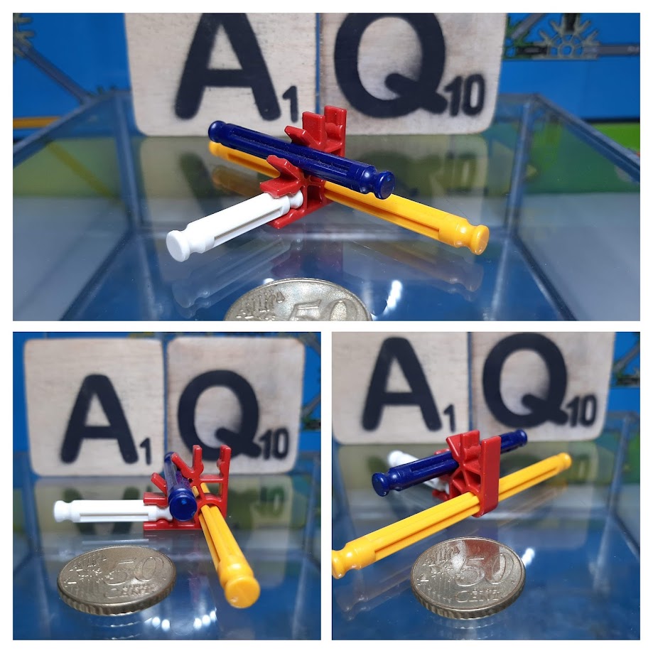
The open-sided socket of a Classic K’NEX connector allows a rod to be snapped into place from the side.
Direction and angles
Connectors do more than hold rods together. Their sockets determine the directions in which rods can extend.
Classic K’NEX connectors are produced in several configurations. The underlying system uses radial connection positions at 45-degree intervals. Depending on the connector, these positions provide straight, right-angle and diagonal directions.
By combining these directions, builders can create squares, rectangles, triangles, diagonals and more complex frameworks.
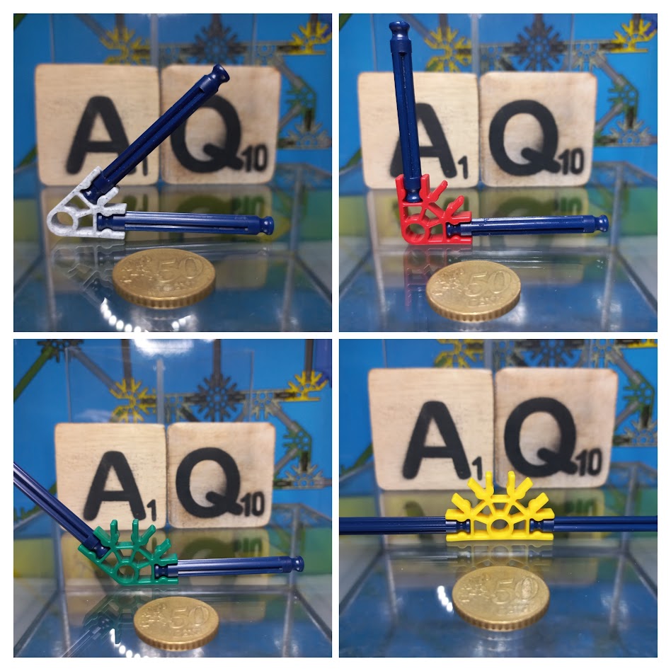
Different connector positions allow rods to extend in predictable directions and angles.
From a flat framework to three dimensions
Many K’NEX structures begin as arrangements of rods and connectors in a single plane. The same connection principle can then be extended into other planes.
Connector elements designed for multi-directional construction allow rods to extend forwards, backwards, upwards and sideways. Flat geometric frames can therefore become three-dimensional structures without abandoning the basic rod-and-connector principle.
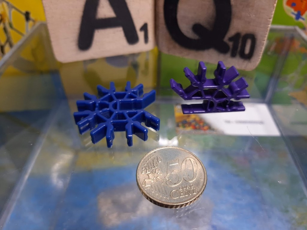
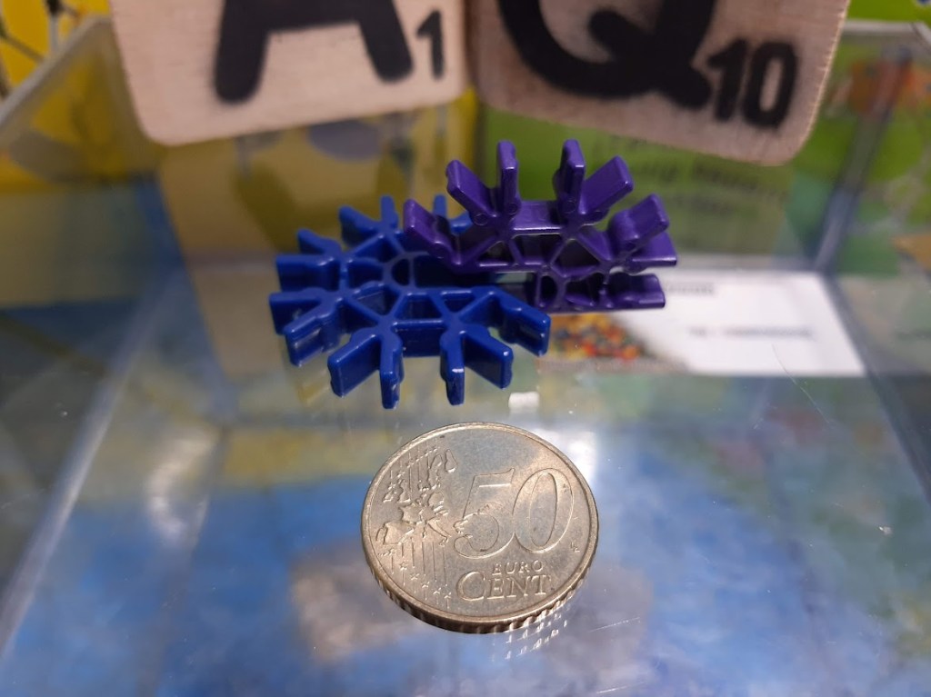
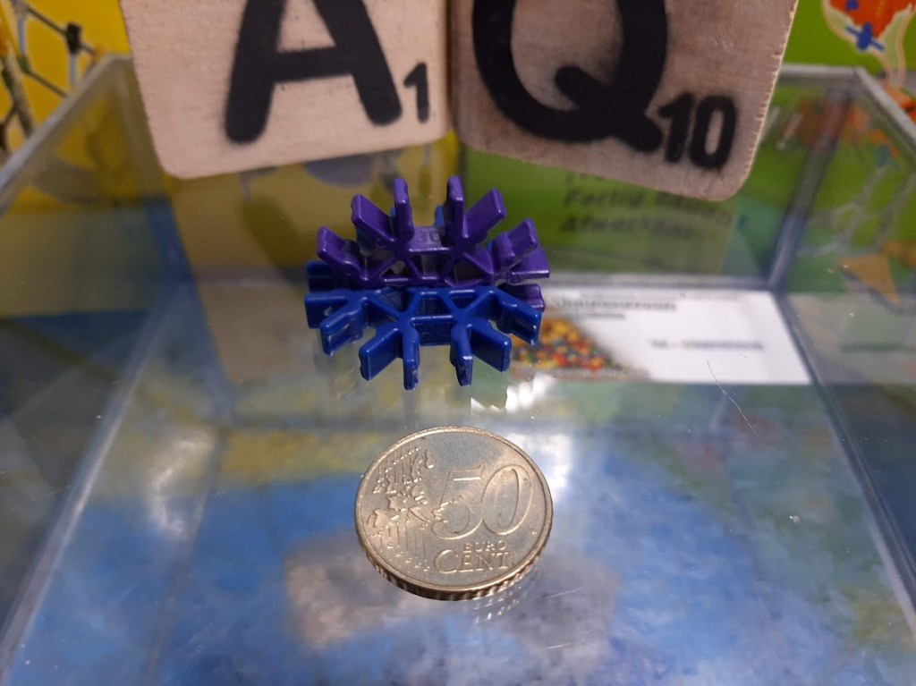
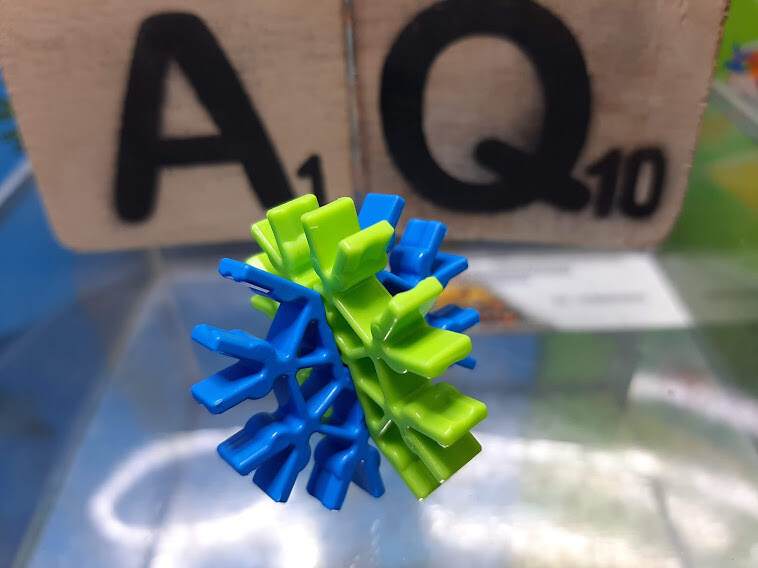
Combining connector elements allows connection points to be created in different planes.
Why rod lengths matter
The standard Classic K’NEX rods form a graduated series of lengths.
For practical identification, K’NEXCHANGE uses approximate nominal lengths of 16, 32, 54, 86, 128 and 190 mm for the familiar six Classic rod sizes.
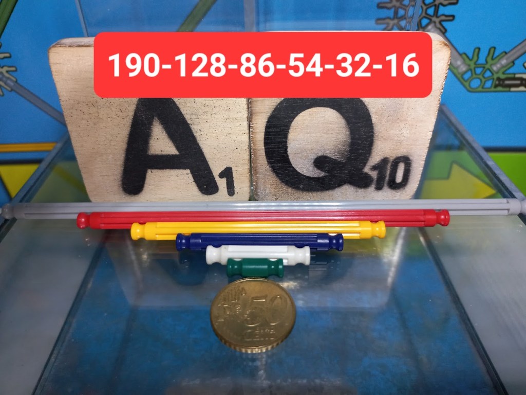
The six familiar Classic K’NEX rod sizes, shown using the approximate nominal measurements used in this catalogue.
Technical patent documentation describes the dimensions more precisely. More importantly, it shows that the rods were not dimensioned independently of the connectors. The effective geometry of a K’NEX framework depends on the distance from the centre of one connector to the centre of the next.
For Classic K’NEX, patent documentation gives a fixed distance of approximately 10.1 mm between the central axis of a connector and the base of its rod socket. The connector therefore contributes to the effective structural distance at both ends of a rod.
This also explains why a physical measurement of a loose rod is not by itself the complete measurement needed to understand K’NEX geometry.
Building with triangles
One of the most interesting consequences of this dimensional system can be demonstrated with right triangles.
When two equal rod-and-connector spans form the perpendicular sides of a right triangle, the next rod size in the sequence can form the diagonal. The progression can then be repeated at larger sizes. The relationship is based on the distances between the centres of the connectors, rather than simply on the lengths of the loose rods.
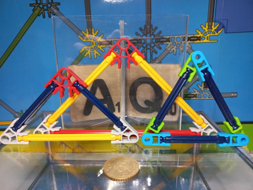
The same geometric principle demonstrated at different scales. Successive Classic K’NEX rod sizes and their connectors allow similar right-triangle relationships to be repeated as the structure becomes larger.
This repeating relationship helps explain how a relatively small selection of standard rod lengths can be used to construct increasingly large regular frameworks.
Triangles also have an important structural role. Adding diagonal members to a framework can increase its rigidity, a principle that K’NEX makes particularly easy to explore in physical models.
Three systems, different scales
K’NEX has been produced in three principal building systems discussed elsewhere in this catalogue: Kid K’NEX, Classic K’NEX and Micro K’NEX.
They are not simply three different colour schemes. Their components differ substantially in size and design.
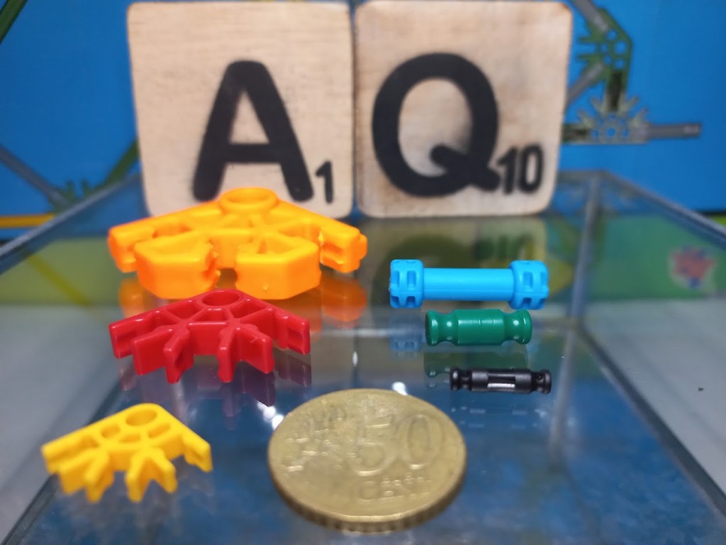
Kid K’NEX, Classic K’NEX and Micro K’NEX components shown together for scale. The €0.50 coin provides a common size reference.
Classic and Micro are especially interesting from a technical perspective. Patent documentation describes separate connector dimensions for the two systems while applying the same underlying geometric progression to their rod lengths. It gives approximately 10.1 mm from connector centre to socket base for Classic and approximately 6.12 mm for Micro.
The relationship goes further: the patent explains that, from part of the Micro rod sequence onward, centre-to-centre distances were arranged to correspond with those of Classic. This helps explain why carefully designed transition components can connect the two scales in useful ways.
Extending the basic geometry
Many specialised K’NEX parts extend the rod-and-connector system rather than replacing its basic principles.
Panels are a particularly clear example. K’NEX patent documentation describes panels with connecting tips shaped to engage with standard connector sockets. Certain opposing connection points can span the same distance as a standard rod, allowing the panel to take the place of a rod in particular arrangements.
A panel can therefore have both an aesthetic and a structural function. In some arrangements it can provide diagonal bracing and increase the rigidity of a framework.
Other components extend K’NEX in different ways. Clips provide additional connections, hinges allow movement, and wheels, gears, pulleys, chains and motors introduce mechanical functions. Transition and adapter parts allow otherwise different construction systems or scales to interact.
Simple principles, complex structures
The technical strength of K’NEX comes from repeatedly combining a small set of predictable properties.
Rods provide defined distances. Connectors provide defined directions. Their snap-fit connection allows frameworks to be assembled, modified and dismantled. The relationship between rod lengths and connector dimensions makes repeating geometric structures possible.
Specialised components then add new possibilities without removing those underlying principles.
The result is a construction system in which simple individual components can be combined into structures, mechanisms and models far more complex than the individual parts themselves.
Technical sources
The technical explanations on this page are based primarily on patent documentation for the K’NEX rod-and-connector construction system and subsequent developments.
Glickman, US Patent 5,061,219 — foundational K’NEX rod-and-connector system. Glickman, US Patent 5,199,919 — further foundational construction-system geometry. US Patent 6,089,941 — Panels for construction toy set — snap-fit connector construction and structural/aesthetic use of K’NEX panels. US Patent Application 2008/0090485 — Offset matrix adapter for toy construction sets — detailed Classic and Micro dimensions, connector-centre geometry and rod-length progression.
Patent documents describe technical implementations and dimensions at particular points in the development of the K’NEX system. Individual components and later product variants may differ.
Related: For a general introduction to the building system, see What is K’NEX? For individual components, see Parts.
 K'NEXCHANGE