More Tips & Tricks
Looking for a specific tip? Use your browser’s Find function to search this page by part name, building technique or topic: Ctrl+F on Windows or Command+F on Mac.
Once you are familiar with the basic K’NEX connections, small adjustments can make a surprisingly large difference. Wheels can run more freely, gears can mesh more smoothly, chains can stay aligned and powered models can become much more reliable.
This page collects practical tips for moving parts, roller coasters, flexible components, motors and troubleshooting. Some techniques apply only to particular K’NEX systems or generations, so always check which parts and instructions belong to your model.
Wheels: fixed or free to rotate?
Before building an axle, decide what is supposed to rotate.
A wheel can rotate freely around a stationary rod or axle, or it can be fixed so that the wheel and axle rotate together. These two arrangements may look similar but behave very differently.
An interlocking clip can be used in suitable Classic K’NEX arrangements to make a wheel or another component turn with a rod.
For a free-running wheel, make sure the wheel is retained on the axle without being squeezed against the surrounding structure.
After assembly, turn the wheel by hand. It should move as intended without unnecessary resistance.
Use spacers to position moving parts
Spacers are small, but they can be important in mechanisms.
They can keep wheels, gears and pulleys in the correct position and prevent unwanted sideways movement along an axle.
Too much sideways movement can cause gears to lose alignment. Too little space can create friction.
The aim is therefore not simply to fill every available gap. Use enough spacing to keep the mechanism aligned while allowing the moving parts to rotate freely.
Check gears before adding power
Gears should mesh securely without being forced tightly together.
After building a gear train, rotate it gently by hand before connecting or switching on a motor.
Check that:
- all gears rotate;
- the teeth engage correctly;
- axles remain parallel where required;
- gears do not press excessively against connectors or spacers;
- nothing rubs against the surrounding structure.
If the mechanism becomes difficult to turn, find the source of the resistance before adding power.
A motor should drive the mechanism — it should not have to overcome a construction error.
Changing speed and turning force
Different gear sizes can be combined to change the behaviour of a mechanism.
A small gear driving a larger gear generally reduces rotational speed while increasing the available turning force. A larger gear driving a smaller gear generally increases speed while reducing the available turning force.
This can be useful when a model needs either slower, stronger movement or faster rotation.
The same principle can be applied in several stages using a gear train.
Always check that the resulting mechanism can rotate freely before applying power.
Chains
K’NEX chains are assembled from individual links and can transfer movement between separated parts of a model.
When building a chain:
- connect the links consistently;
- check that no link is twisted;
- make sure the chain follows the intended path;
- avoid excessive tension;
- check that the chain remains engaged with the appropriate gears or sprockets.
A chain that is too loose may leave its intended path. A chain that is too tight can increase friction and place unnecessary load on the mechanism.
Turn the mechanism slowly by hand through a complete cycle before using a motor.
Guiding a chain
Long chain runs and coaster lifts may need additional guidance.
Some K’NEX constructions use guides to help keep the chain centred and prevent it from moving sideways.
If a chain repeatedly leaves its intended path, do not immediately shorten it. First check the alignment of the gears, guides and surrounding structure.
A structural section that is slightly out of alignment can sometimes be the real cause of a chain problem.
Pulleys, belts and elastic loops
Pulleys transfer movement without requiring two gears to mesh directly.
Depending on the construction, a flexible belt, cord or suitable elastic loop can connect the pulleys.
Alignment matters. If two pulleys are not positioned correctly, the belt may move sideways or come off.
As with gears and chains, test the mechanism manually before adding power.
Flexible rods and tubes
Flexible components allow curves that cannot be produced with ordinary rigid rods.
Do not assume that every flexible K’NEX component is interchangeable. Different systems and sets can use different profiles, lengths and connection methods.
Flexible tubes can sometimes be guided with suitable clips or other support points.
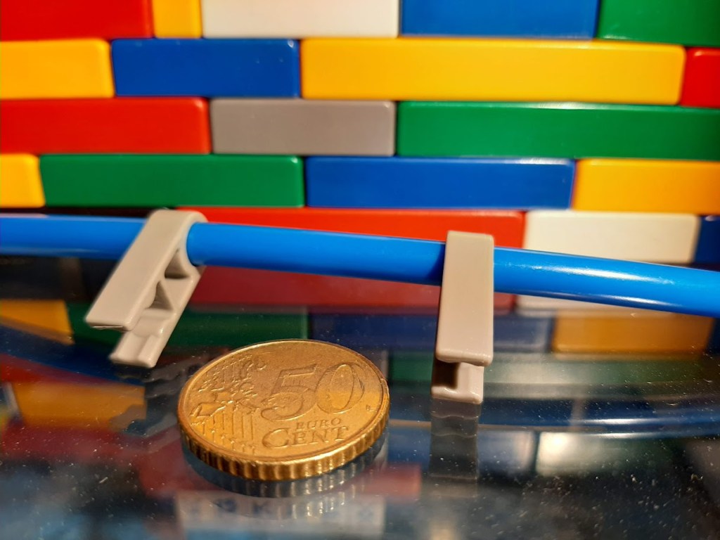
When creating a curve, try to distribute the bend gradually. A smooth curve is generally more useful than forcing most of the bend into one small area.
Making a loop with flexible tubes
Some flexible tubes can be combined with small rods or transition components to create closed curves or circular arrangements.
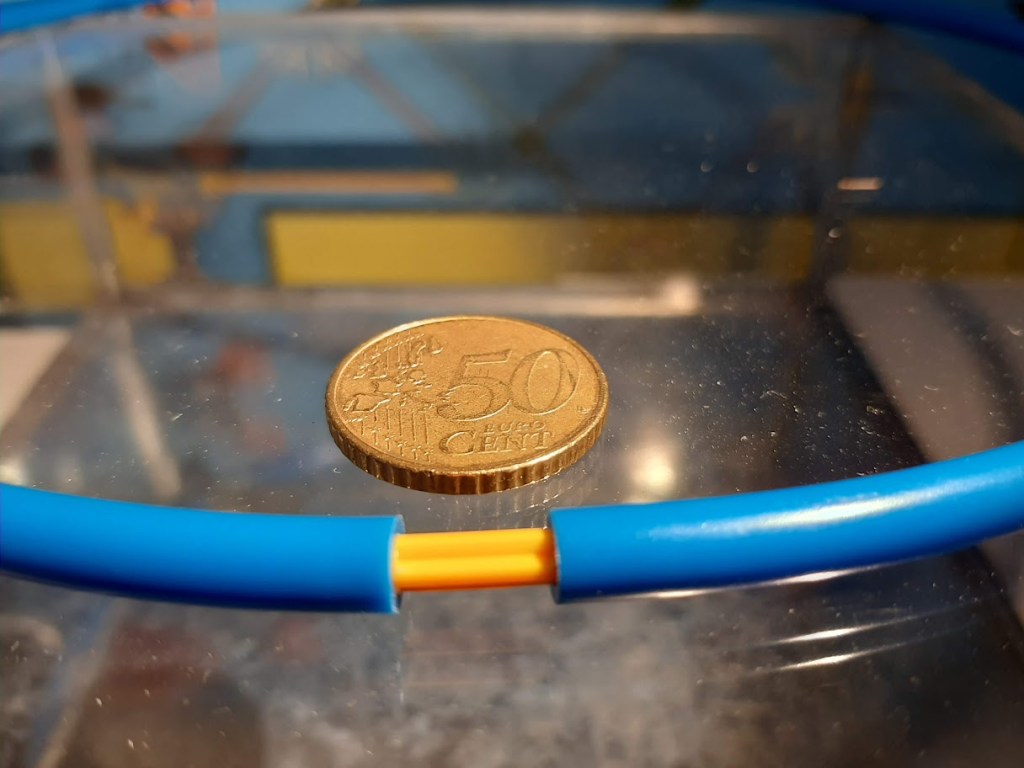
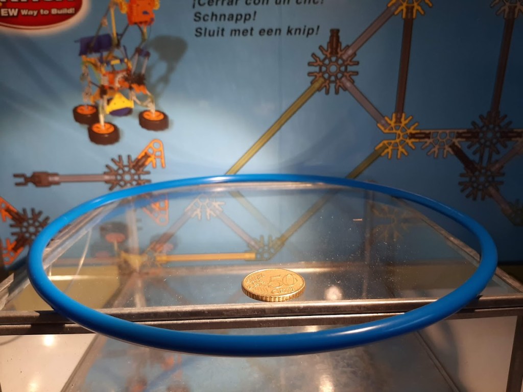
Check that the ends remain securely connected and that the curve does not place excessive force on one connection point.
The exact method depends on the type of tube and the components available.
Roller-coaster systems
K’NEX has used different roller-coaster systems over time.
Before troubleshooting a coaster, first identify:
- whether the main construction uses Classic or Micro K’NEX;
- the type of track;
- the coaster car;
- the lift or launch mechanism;
- the chain system, if present.
A solution for one coaster system should not automatically be applied to another.
Support the track
A coaster car needs a predictable path.
If track changes position as the car passes, the problem may be the supporting structure rather than the car itself.
Check that supports are sufficiently rigid and that adjoining track sections create a smooth transition.
Triangles and diagonal braces can help prevent larger support structures from deforming.
Also inspect curves and changes in slope. A small misalignment can have a much greater effect when the car is moving at speed.
Test the coaster gradually
Do not begin troubleshooting by repeatedly releasing the car from the highest point.
Start with a shorter section.
Test the car on:
- a straight section;
- a gentle slope;
- a curve;
- a transition between sections;
- progressively longer parts of the complete track.
This makes it much easier to discover where unwanted resistance, misalignment or instability begins.
Connecting Micro coaster cars
Some Micro K’NEX coaster cars can be joined using a dedicated coaster car link.
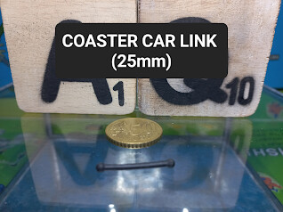
One documented link is part number 24161.
These small links can become damaged or may be missing from an older collection.
When restoring an original set, the correct link remains the preferred component.
A temporary coaster-car workaround
For experimentation, a small flexible connection can sometimes provide a temporary substitute when an original coaster-car link is unavailable.
For example, a short piece of elastic with secured ends can be used experimentally to connect two cars.
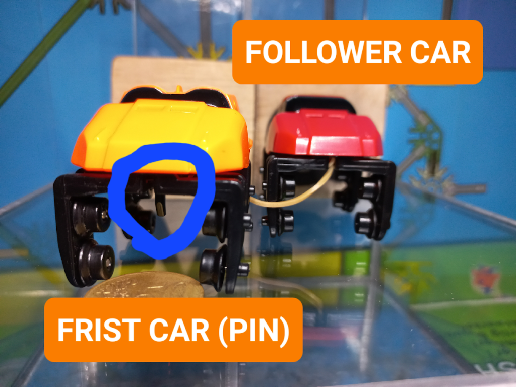
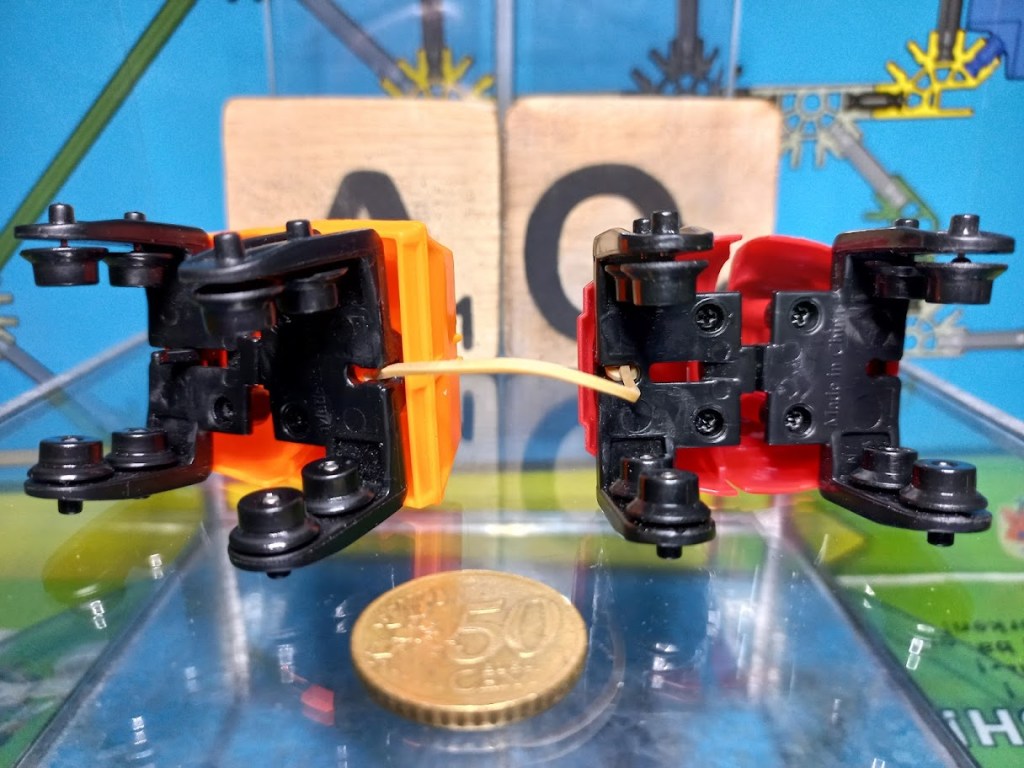
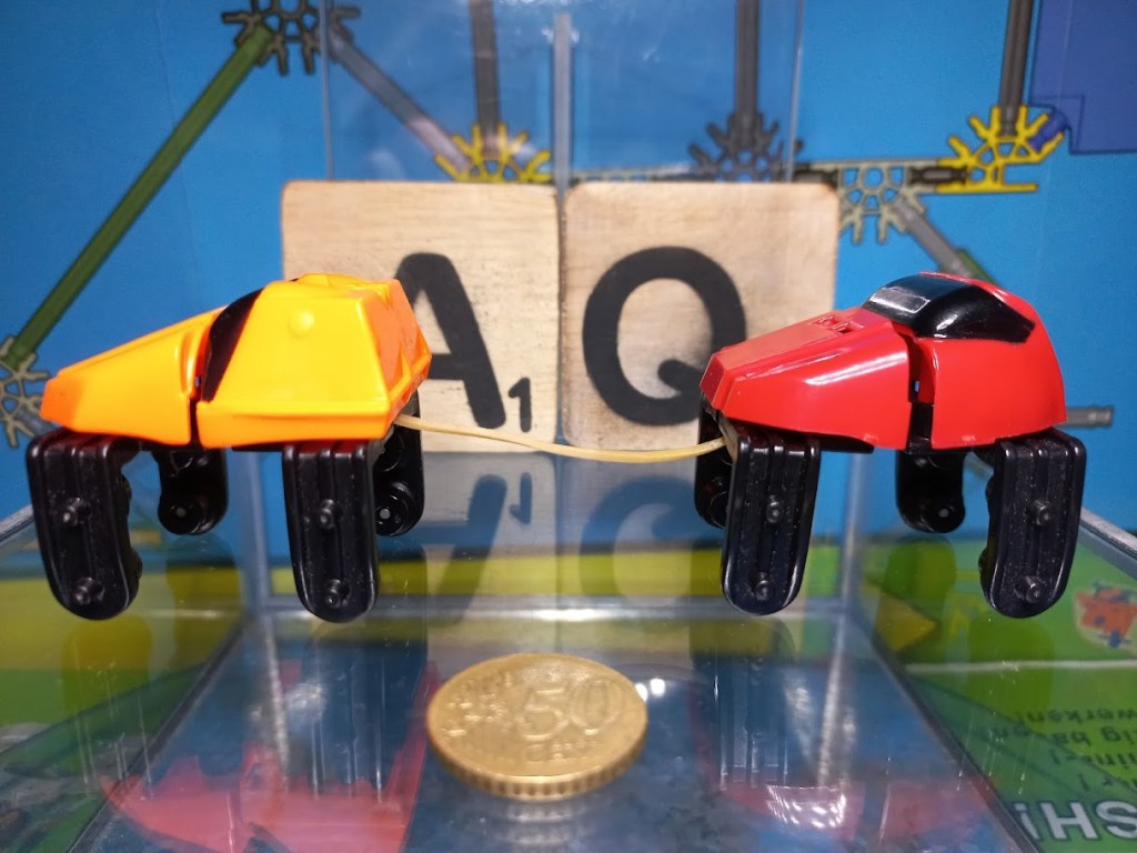
This is a practical workaround, not an original K’NEX component. It should not be recorded as part of the original set contents and may behave differently from the purpose-designed link.
For restoration and cataloguing, always distinguish original components from substitutes.
Check coaster cars as well as track
If a coaster car repeatedly stops or derails at different locations, the problem may not be the track.
Check the car for:
- free movement of wheels or rollers;
- damaged or missing components;
- parts rubbing against the track;
- incorrect assembly;
- problems with a chain-lift connection where applicable.
Testing another compatible car on the same section can help determine whether the problem is in the car or the track.
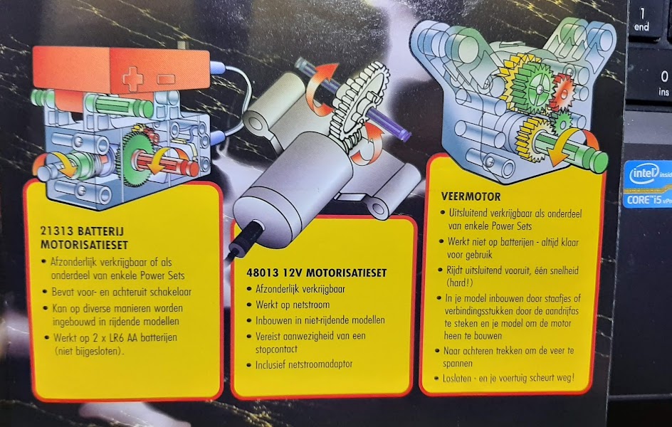
Motors
K’NEX has produced several different motor systems and powered components.
They differ in housing, power supply, speed, gearing, connections and intended use. Some are battery powered, while other systems use mains adapters or different forms of stored or generated energy.
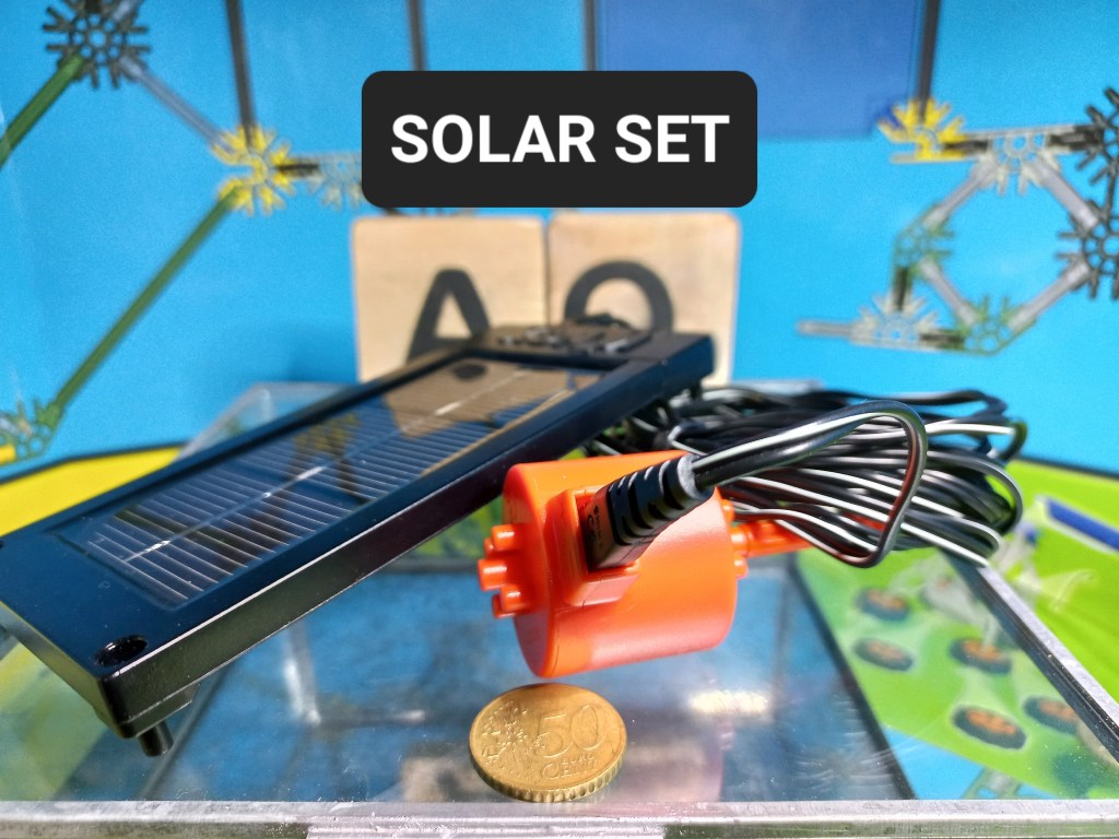
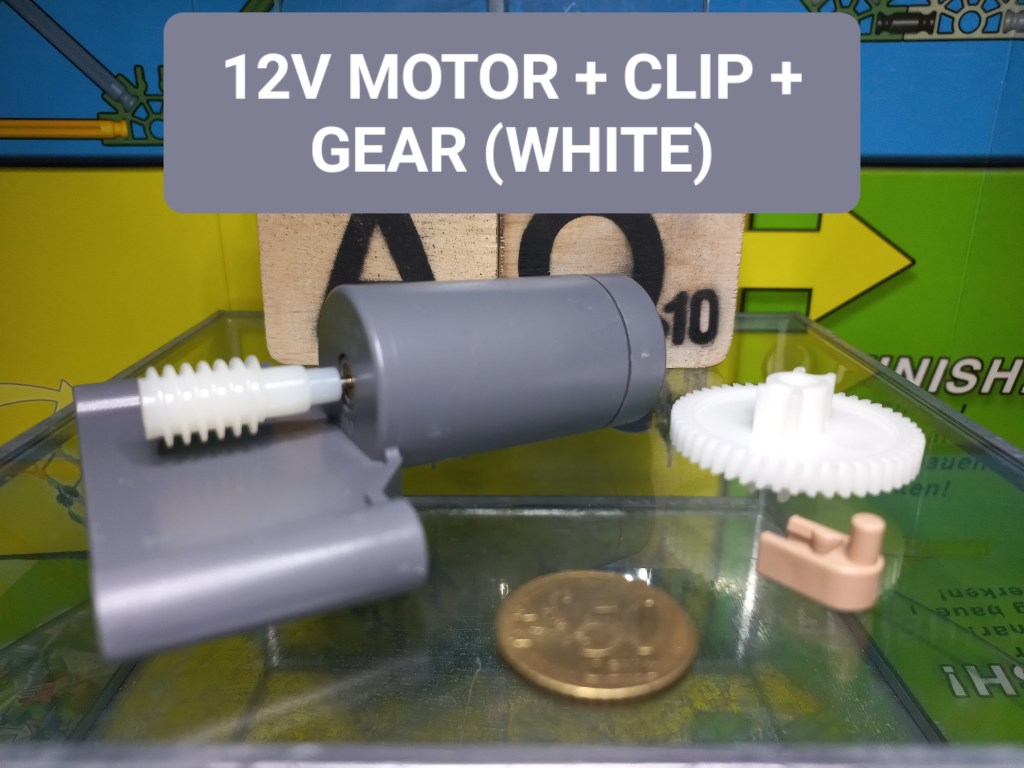
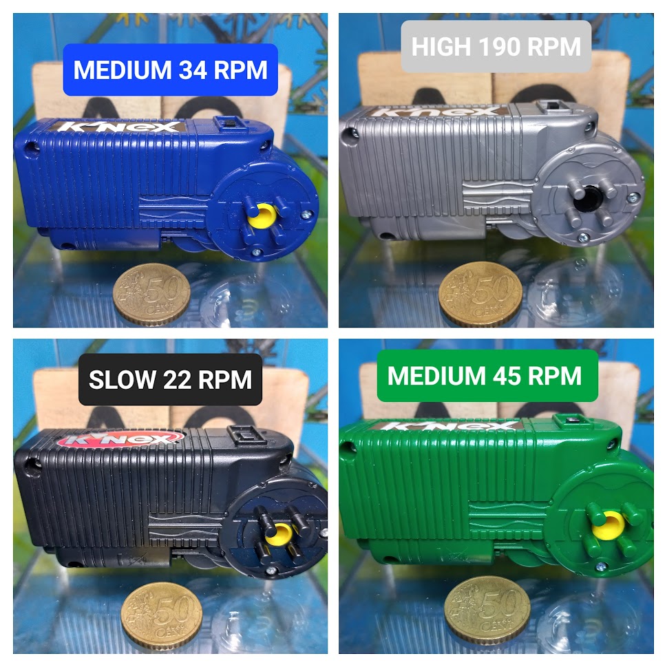
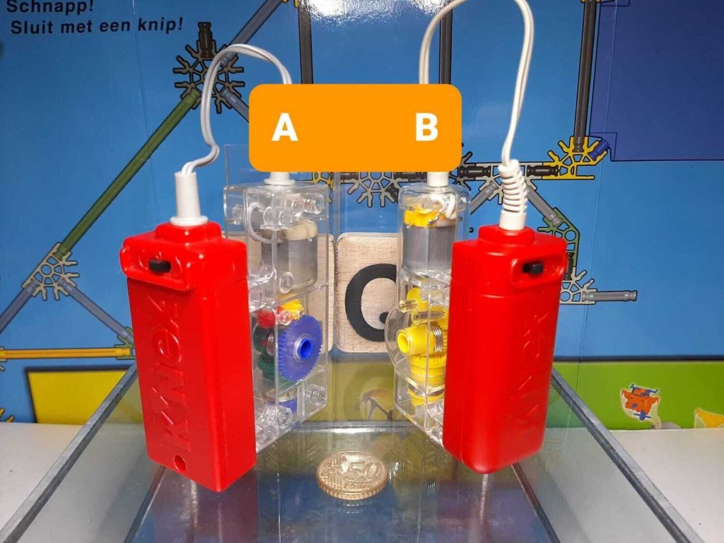
Do not assume that instructions for one motor apply to another.
Some early or educational motor housings are transparent, making the internal gears visible. These provide a useful way to observe how a motor’s high-speed rotation is reduced and transferred through a gear train.
Before switching on a motor
First test the complete mechanism by hand where possible.
Check that:
- rods and axles can rotate;
- gears mesh correctly;
- chains follow their intended path;
- wheels and pulleys do not rub;
- nothing is trapped;
- the structure is sufficiently rigid;
- wires are clear of moving components.
If the mechanism is already difficult to move manually, investigate the cause before applying motor power.
Batteries
Different K’NEX battery motors can have different battery compartments and opening mechanisms.
Always consult the original instructions for the particular motor or set before opening the battery compartment or replacing batteries.
Use the battery type and orientation specified for that motor.
Do not assume that a battery-replacement procedure shown for one K’NEX motor applies to another.
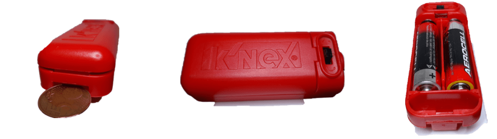
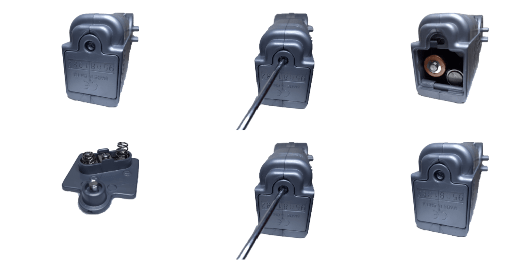
Some battery covers use screws; others use different opening mechanisms. Use an appropriate tool and avoid damaging the cover or fastener.
If a powered model does not work
Troubleshoot systematically.
First separate the possible causes:
Power — Are the correct batteries or power supply being used?
Motor — Does the motor operate without the mechanism attached, where the design and original instructions allow this to be checked safely?
Transmission — Can the gears, chain or pulleys move freely?
Structure — Are the axles aligned and properly supported?
Load — Is the mechanism asking the motor to move more resistance or weight than intended?
Changing several things at once makes the cause harder to identify. Test one part of the system at a time.
Missing parts and substitutes
Older K’NEX sets sometimes contain specialised components that are difficult to replace.
A temporary substitute can be useful when experimenting or testing a construction, but it should be treated differently from an original component.
Ask three questions:
- Does the substitute perform the required function?
- Can it be used without damaging the original K’NEX parts?
- Is it clearly identified as a substitute rather than an original set component?
For a restored display model, a substitute may sometimes be acceptable to the builder. For documenting original set contents in a catalogue, it is not equivalent to the original part.
Small problems often have simple causes
When a model does not work as expected, check the simplest possibilities first.
Look for:
- a connector facing the wrong direction;
- a rod connected in the wrong opening;
- a missing spacer;
- an axle pushed too tightly against the frame;
- gears that are not aligned;
- a twisted chain link;
- track that has moved;
- a loose connection in a supporting structure;
- a component from the wrong K’NEX system.
Many problems that appear to involve a specialised component actually begin with a basic connection or alignment error.
Change one thing at a time
K’NEX is particularly useful for experimentation because constructions can be changed and rebuilt.
When trying to improve a mechanism, change one thing at a time and test again.
Move a spacer. Change one gear. Add one brace. Adjust one track support.
If several things are changed simultaneously, it becomes difficult to know which change solved — or caused — the problem.
This simple method turns troubleshooting into experimentation and makes it easier to understand how the construction works.
Keep original instructions as a reference
Even experienced builders can benefit from checking the original instructions.
They can help establish:
- the intended component;
- quantity;
- connector orientation;
- spacing;
- gear arrangement;
- chain path;
- track configuration;
- motor installation;
- and the sequence in which complex sections were assembled.
For available instructions, see Online Manuals.
For basic building techniques, see Tips & Tricks.
For the geometry and construction principles behind rods and connectors, see How K’NEX Works.
 K'NEXCHANGE