Looking for a specific tip? Use your browser’s Find function to search this page by part name, building technique or topic: Ctrl+F on Windows or Command+F on Mac.
K’NEX is easy to start with, but a few building techniques can make models easier to assemble, stronger and more reliable. This page introduces useful tips for working with rods, connectors and other common K’NEX parts.
You do not need to learn everything at once. Start with the basic connections, check your work as you build, and move on to more specialised techniques when you need them.
Start with rods and connectors
Rods and connectors form the basic framework of most Classic K’NEX constructions.
A rod provides a distance between connection points. A connector joins rods and determines the directions in which they can extend.
K’NEX connectors are often described by the number of available rod connection positions, or ways. For example, an 8-way connector provides eight positions around the connector for attaching rods.
Do not rely on colour alone when identifying a part. K’NEX components have been produced in many alternative colours and finishes.
Three common rod-to-connector connections
A Classic rod can interact with a connector in several ways.
The familiar connection is made by snapping the end of the rod sideways into one of the open connector sockets. Rods can also be used with other openings and connection features where the design of the component allows it.
Learning to recognise these different connections makes instructions easier to understand and opens up more building possibilities.
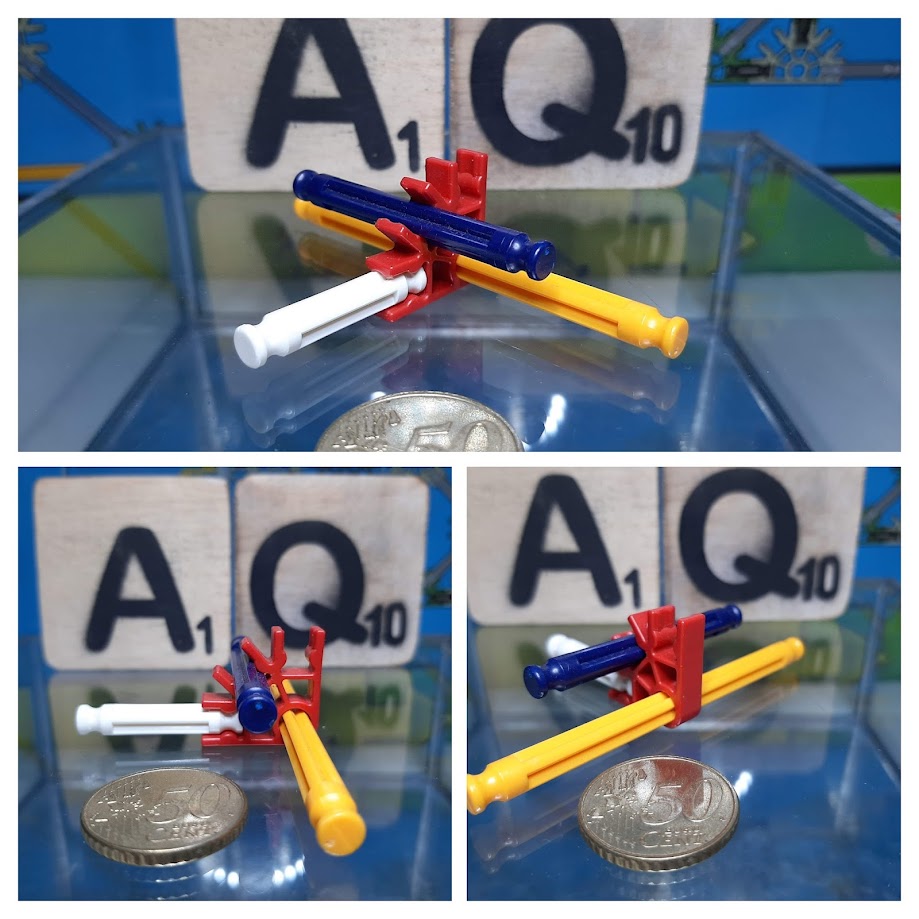
When following instructions, look carefully at how the rod is connected rather than only checking whether you have used the correct rod and connector.
Check the direction of connectors
One of the easiest building mistakes is to use the correct connector in the wrong orientation.
Two connectors may look identical at first glance but point their rod positions in different directions when rotated or reversed. This becomes especially important in three-dimensional structures.
If a later rod appears not to fit, do not immediately force it into position. First compare the orientation of the nearby connectors with the instructions.
A small mistake several steps earlier can cause a much larger alignment problem later.
Numbers in instructions usually show quantities
In a K’NEX instruction manual, a number shown beside a part in the parts list usually indicates the quantity required, not the part number.
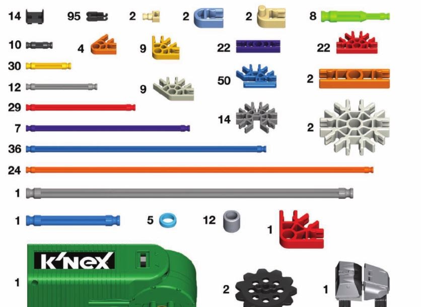
Part numbers are useful for cataloguing and identifying components, but they are not normally what a builder needs to read while following an illustrated construction sequence.
Building in three dimensions
Flat K’NEX frames can be extended into three-dimensional structures.
Classic K’NEX includes specialised 3D connector elements. Common versions provide four or seven rod positions and include a slot that allows two compatible connector elements to be joined.
Align the two parts correctly, slide them towards each other and press them together until they are securely connected.
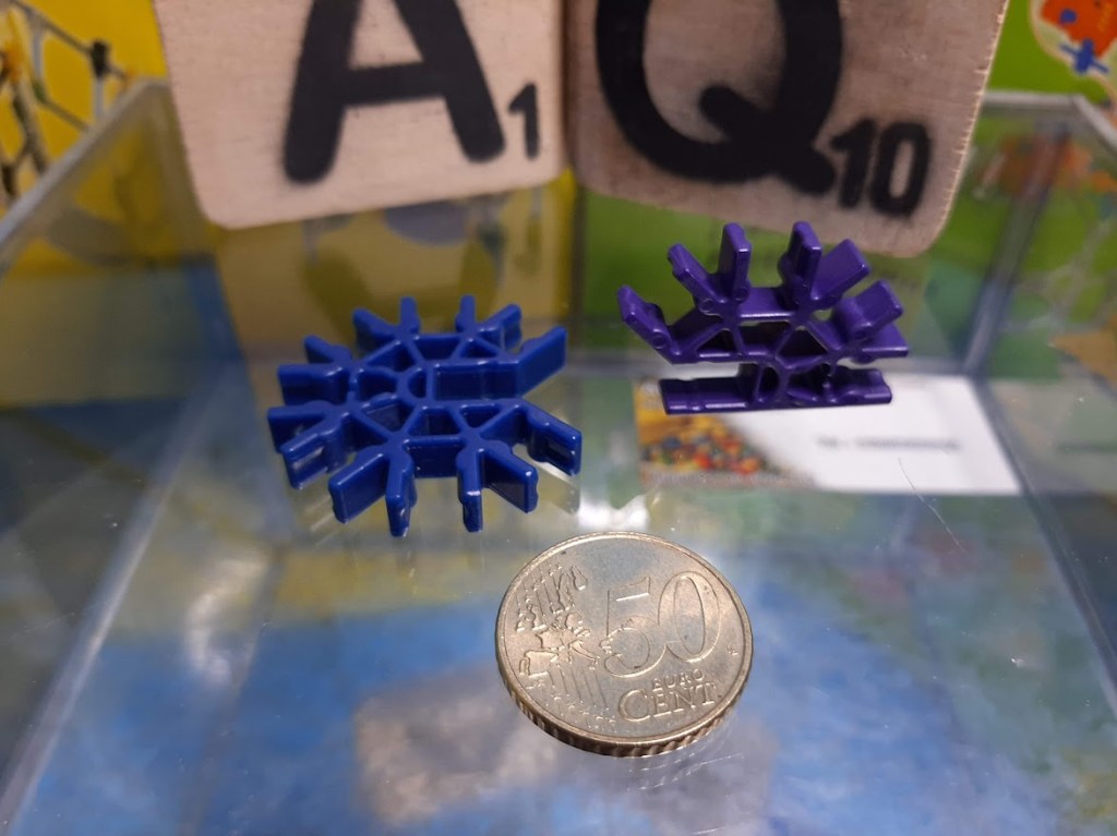
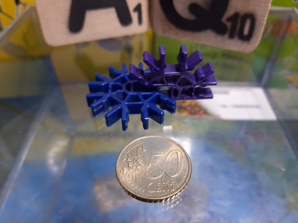
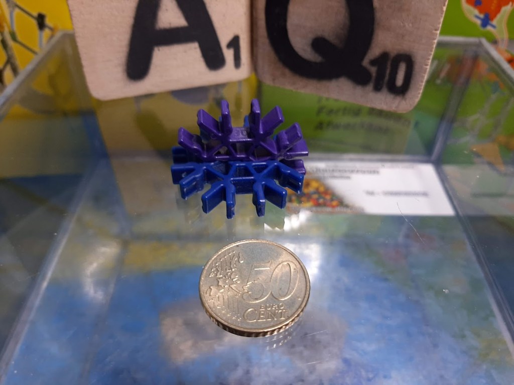
The resulting connection provides rod positions in different planes.
When building a complex 3D model, check the orientation before adding many rods. Correcting one connector is easy; correcting the same connector after several sections have been attached can require considerable disassembly.
Make structures stronger with triangles
A rectangular frame can change shape if its corners are able to move. Adding a diagonal creates triangles and can make the structure much more rigid.
This is one of the most useful techniques for strengthening towers, bridges, supports and other large K’NEX frameworks.
Before adding large numbers of extra parts, look for places where a diagonal brace can prevent a frame from deforming.
For the geometry behind this principle and the relationship between K’NEX rod lengths and connector positions, see How K’NEX Works.
Build repeated sections separately
Large K’NEX models often contain repeated frames, sides, towers or supports.
Where practical, build identical sections separately and compare them before joining them together. This can make mistakes easier to spot and reduces the amount of a large model that must be dismantled if something is wrong.
Before connecting the modules, check that corresponding connectors point in the same directions.
Classic, Micro and Kid K’NEX are different systems
K’NEX has three principal building systems: Classic K’NEX, Micro K’NEX and Kid K’NEX.
Their components differ in size and should not be assumed to fit together directly.
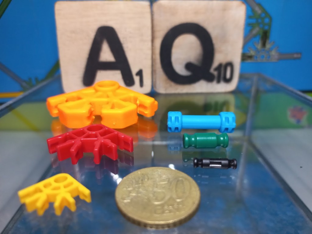
Some purpose-designed parts allow Classic and Micro components to meet. These include transition rods, reducers and adapters.
This can be particularly useful in sets that deliberately combine both systems.
Connecting Classic and Micro
There is more than one type of transition between Classic and Micro.
A transition rod can provide a connection between components of the two systems.
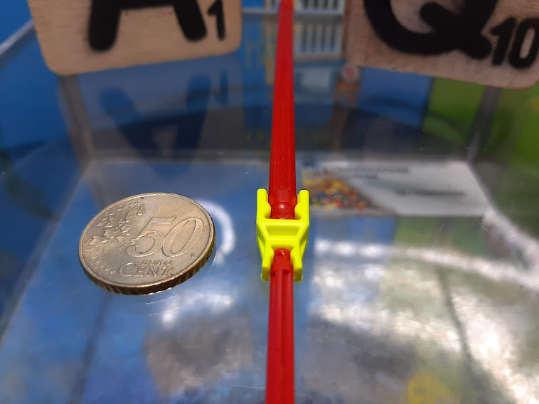
Other adapters or reducers allow different rod or connector arrangements to meet.
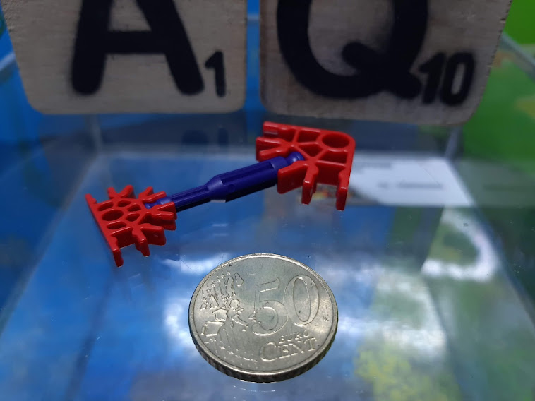
Identify both ends of a transition component before using it. A part designed to solve one Classic-to-Micro connection problem does not necessarily solve another.
Locking a rod connection
Some constructions benefit from additional security at a rod-and-connector connection.
A rod lock can be used in suitable arrangements to help secure the connection.
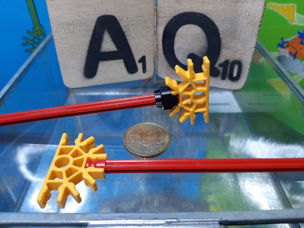
Do not add locking components automatically everywhere. Use them where the design or function of the model requires the additional support.
Fixed wheel or free-spinning wheel?
A wheel does not always need to behave in the same way.
In some constructions the wheel should rotate freely around an axle. In others, the wheel should rotate with the rod or axle.
An interlocking clip can be used in suitable Classic arrangements to lock a wheel or other component so that it turns with the rod.
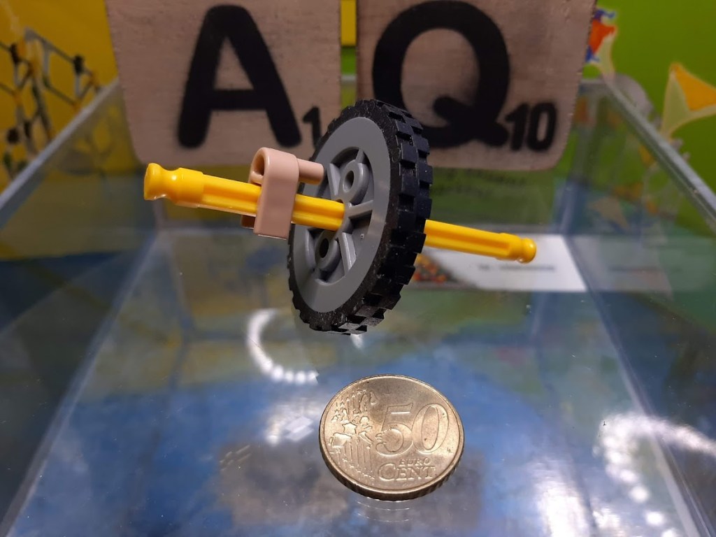
This distinction is important when building vehicles and mechanisms: first decide whether the axle or the wheel is supposed to rotate.
Give moving parts enough space
Wheels, gears and pulleys need to remain correctly positioned on their axles, but moving components should not be squeezed so tightly that they cannot rotate freely.
Spacers and clips can help position components.
After assembling a mechanism, turn it gently by hand. Check that:
- axles rotate freely;
- gears remain aligned;
- gears mesh without being forced together;
- wheels do not rub unnecessarily against the frame;
- spacers and clips prevent unwanted sideways movement.
Solve excessive resistance before adding motor power.
Do not force a mechanism
If a K’NEX mechanism does not move freely, applying more motor power is rarely the best first solution.
Disconnect or switch off the power and check the mechanism by hand. Look for misaligned axles, gears pressed too tightly together, incorrect spacers, rubbing wheels, twisted chains or structural parts that have moved out of position.
A freely moving mechanism is generally easier to diagnose and more reliable when power is added.
Useful small-part tricks
Some small K’NEX components can be awkward to remove or handle.
A tightly fitted snap cap, for example, can sometimes be removed more easily by using a suitable connector to gain leverage rather than pulling only with your fingers.
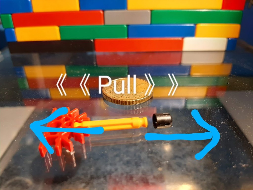
Brick-compatible K’NEX parts can also be difficult to separate. A suitable brick separator can make this easier and reduces the temptation to pry parts apart with unsuitable tools.
Hinges, links and hole-end clips
Small specialised parts can solve connection problems that rods and standard connectors cannot.
Hinges allow controlled movement or a change of angle. Links can create flexible connections. Hole-end clips can provide attachment or guide points.
A hole-end clip can, for example, be useful for guiding certain flexible tubes.
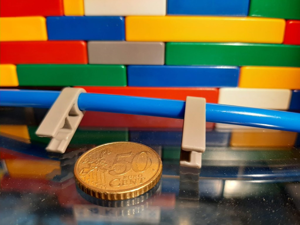
These components are often most useful when you first think about the function required — pivot, guide, retain or connect — and then choose the appropriate part.
Roller coasters need their own techniques
K’NEX roller coasters use several different track, car and lift systems. A technique that works with one system may not work with another.
Before troubleshooting a coaster, identify:
- whether the construction uses Classic or Micro components;
- the type of track;
- the coaster car;
- the lift or launch system;
- the chain and guides, if present.
Track alignment, structural support and smooth transitions are especially important for reliable operation.
More detailed guidance will be collected on Roller Coaster Tips.
Missing a specialised part?
When restoring an old model, specialised components can sometimes be difficult to find.
A temporary workaround can occasionally help with testing, but it should be clearly distinguished from the original K’NEX solution.
For example, Micro coaster cars were produced with dedicated links for joining cars. A simple flexible connection may sometimes be useful for experimentation when an original link is unavailable, but it should not be mistaken for the original component or documented as original set contents.
For catalogue identification and restoration, always distinguish between original parts and later substitutes.
Motors and powered models
Before working on a powered model, make sure the mechanical construction moves correctly without power.
Different K’NEX motors use different power supplies, battery compartments and operating arrangements. Do not assume that instructions for one motor apply to another.
When replacing batteries or opening a battery compartment, consult the original instructions for that motor or set first.
More detailed information about motor types, batteries, gearing and powered models will be collected separately under Motors & Power.
Keep the instructions nearby
When building an original K’NEX model, use the instruction manual as more than a sequence of pictures.
Compare:
- the parts;
- quantities;
- connector orientation;
- connection method;
- rod positions;
- repeated sections;
- the overall shape of the structure.
If something no longer fits several stages later, checking the most recent steps is usually more productive than forcing the next connection.
Online instructions for many sets can be found through Online Manuals.
Learn by building, testing and changing
Many useful K’NEX techniques become easier to understand when you can see what changes in a real structure.
Build a frame and add a diagonal. Turn an axle before and after changing its spacers. Compare a free-spinning wheel with a locked wheel. Rotate a connector and observe how the available directions change.
K’NEX makes these relationships visible because a construction can be assembled, tested, changed and rebuilt.
For a technical explanation of the geometry and connections behind the building system, see How K’NEX Works.
 K'NEXCHANGE